
Getting Started With Anderson Powerpoles
About Powerpoles
Anderson Power Products invented the Powerpole® and these connectors are widely used on DC power cables. They are popular with amateur radio operators because:
- parts are readily available
- the parts are easy to assemble on your own cables
- the connector doesn’t have a plug variation and a socket variation, any connector can connect to any other connector
- once assembled in pairs the connection is not reversable, making it impossible to accidently reverse power polarity by connecting the plug backwards
- the contacts are mechanically and electrically reliable, and corrosion resistant
- a variety of hardware parts are available to mount them onto plates, boxes, or panels
- they are easy to connect and disconnect, but can also be pinned together for a semi-permanant installation
- the contacts are durable, rated for tens of thousands of insertions
- amateur radio operators have lots of equipment that runs on 12V DC
Many amateur radio groups have adopted Powerpoles as their standard power connector (ARES, RACES, and many clubs and associations). Standardization eliminates the need for adapters when equipment from different operators is used together in an emergency, public service event, or contest.
There are some downsides to Powerpoles:
- genuine parts are somewhat expensive
- they are not rated for ingress protection from dust or water. If this is required in your application, consider using MC4 connectors.
This guide will help you better understand what Powerpoles are and how to assemble your own power cables with Powerpole connectors. We’ll discuss what tools and supplies you’ll need, and I’ll walk you step by step through building your first cable.
Anatomy of Powerpoles
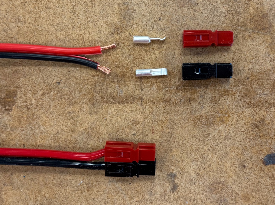
The housing is a precision molded plastic part available in many colors. For DC power connections we typicaly use red for positive and black for ground. Inside there is a socket into which you insert a contact. Housings are manufactured to hold a single contact, or in a permanently connected assembly which can hold two contacts. The housings are cleverly molded such that they can be friction fit together side by side or top to bottom. The housings come in multiple sizes, but the one you want for the vast majority of amateur radio use cases accommodates 15, 30, or 45 amp contacts.
The contact is a silver plated metal part with a cupped blade on one end and a receiving barrel (or slot on the 45 amp contacts) on the other. Some people call the cupped end of the blade the tongue. After crimping the barrel to a wire, you insert it into a housing. Contacts come in three sizes, 15 amp, 30 amp, and 45 amp. Each of the three sizes of contact fits into the same housing. The difference between the contacts is the size of the barrel, and therefore the guage of wire that the barrel can be securely crimped to:
- use 20-16 guage wire with 15 amp contacts
- use 14-12 guage wire with 30 amp contacts
- use 10 guage wire with 45 amp contacts
When two housings are friction fit together, a roll pin fits into a void between the two housings, preventing them from separating. If you have a pair of housings connected to another pair of housings (like you would if you connect two cables together), instead of using a roll pin, you can insert a retention clip into the two adjacent voids, which secures the connection and prevents any of the four housings from working loose.
Tools and Supplies
Powerwerx is my go-to place to get Powerpole supplies and accessories. They aren’t a sponsor and I have no relationship with them, I’m just a happy customer.
To install Powerpole connectors onto a cable, you’ll need a few tools.
- Diagonal cutting pliars
- Wire strippers appropriate for the guage of wire you are working with
- A crimper designed for Powerpole contacts, the crimper will have jaws sized for each of the three contact sizes.
- Optional, but recommended, is an inexpensive Powerpole insertion and removal tool. This tool makes it easier to insert a contact into a housing. It’s required if you ever want to remove a contact from a housing (so you can reuse the housing on a different sized contact or different cable).
You may already have diagonal cutters and a wire stripper. If not, there are many options available on Amazon for as little as $10 each. You’ll use these tools to prepare the wire you want to crimp to the contact.
The crimper is more expensive, a great one will be $50, but less expensive options run as low as $30. The crimper should have 3 crimp areas on the die, one for each size (15 amp, 30 amp, 45 amp) of contact.
You’ll need a supply of housings and contacts, the roll pins and retention clips are optional. You can find cheap housings and contacts on Amazon, but it’s pretty likely that you’ll get lower quality knock-offs. The connectors may not be silver coated, which can lead to electrical corrosion. I recommend purchasing the housings and contacts from a reputable vendor who sells genuine Anderson Power Products parts. Here’s some vendors that sell the authentic items:
Finally, you’ll need some wire. Most everyone I know uses zip wire for power cables. Zip wire has two conductors, one insulated in red material, the other in black material, with the two insulators molded together. It gets it’s name because you can easily pull the two insulators apart, permanently “unzipping” the wire. Pick the guage suitable for the current you need. The heavy guage wire is a lot more expensive than the thinner stuff, so I keep various guages of wire on hand.
There are lots of kinds of zip wire, with various conducting and insulating materials. Some brands are stiff, others quite flexible. The brands using aluminum or copper clad aluminum conductors tend to be less expensive than those using pure copper conductors. The more strands in the wire of a given guage tends to be more flexible. There is a wide range of insulating materials used as well. Silicon is more flexible than PVC. I know of no good way to tell how the wire feels from looking at pictures and reading descriptions online. I generally choose conductors made of 100% copper.
If you are just getting started, Powerwerx has a kit which includes a high quality crimper, a supply of housings, various sized contacts, a few roll pins, and some retention clips. The kit includes a nylon carry bag, which is big enough to store the crimper, supplies, and a bunch of wire.
Step By Step Instructions
- The nice thing about making your own cables is they can be exactly the length you want. If you are making a cable for a specific purpose, make it no longer than necessary. Cut the appropriate length of zip wire.
- Unzip one end of your wire about 3 cm
- Using the barrel end of the connector as a measuring guide, strip both wires
- Assemble the red and black housing together by sliding the bump on the side
of the red housing into the slot on the side of the black housing. Make sure
you get them in the correct orientation.
- Take careful note of the orientation as you place your contacts
onto the stripped wire. It’s easy to get them upside down. Position the zip wire so the red and
black wires match up with the housing you just assembled. Orient the connector
so the tongue faces up.
- Crimp one contact onto the wire before repeating the procedure on the second contact.
- Loosely insert both the red and black contacts into their respective housings. If you have an insertion tool, use it to press the contacts, one at a time the rest of the way into their housing. If you don’t have an insertion tool, press both wires firmly into the housing. You’ll hear a faint click when the contacts are fully seated.
Optional procedures:
- You can insert a roll pin into the round hole created by friction fitting two housings together to prevent the housings from shifting during use. Unless you are very concerned about rapid unscheduled disassembly, you’ll be fine without roll pins.
- Some people put hot glue in the housing after they have inserted the connector. Doing so won’t hurt anything, but it’s not required either.
- If you are worried about your zip wire coming unzipped, you can put some heat shrink tubing on the wire before you put the contacts and housings on. I’ve never had wires come unzipped once they had contacts crimped on and inserted into housings, but the shrink tubing does give a more finished look.
- You can purchase inexpensive boots, sized to fit over a pair of connected powerpole housings. These give an even more finished look than heat shrink tubing. But they don’t always stay put, and sometimes slide away from the housings when you pull on them to disconnect two cables.
To see all this in action, check out these videos:
- w2aew How To Install Powerpole Connectors
- Ham Radio Dude’s Guide to Powerpole Install
- The Right Way To Install Powerpoles
Tips and Tricks
- If you can, make your first few cables using either the 15 or 30 amp connectors. The 45 amp connector doesn’t have an enclosed crimp barrel, it’s open on one side to accomodate lower guage wire. The 15 and 30 amp connectors will stay put on the wire while you get it situated in the crimper. The 45 amp connector won’t. It will be easier to manage the 45 amp connector if you already have experience with the smaller connectors.
- For most crimping tools, the 45 amp connector has to be inserted with the open part of the crimp barrel facing up. That means the tongue on the other end of the connector will be facing down. It’s easy to get the connectors in the wrong orientation (i.e. when the tongues are pointing up, the red wire will be on the right). Pay careful attention to avoid wasting connectors.
- Don’t solder your connectors to the wire. Crimping makes a physically stronger and electrically better connection.
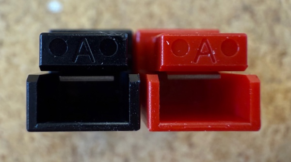
- The design of Powerpoles allow you to put red on the left or red on the right.
To ensure you are interoperable with other equipment you need to have the
corrent orientation. When looking at the end of the housing, you’ll see a
molded in “A”. When you can read the “A”, the pair of red/black housings should
have red on the right.
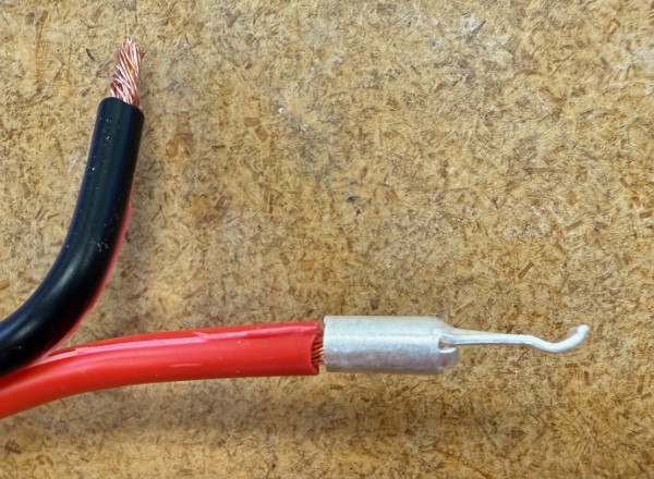
When you crimp the contact on, the curved or cupped part of the blade should
be facing up like it could catch a little drop of water. If the A is oriented
correctly so you can read it normally, use this phrase to help you remember:
“Red on right, tongue on top”. Another easy way to remember this is to
assemble a couple of red/black pairs of empty housings in the proper
orientation, and keep them in with your other Powerpole supplies. Then you can
always look at a properly assembled connector when you are making a new one.
- Make sure that both the wire and the contact are properly sized for your current and length requirements. If you put 35 amps of current into a 5 meter wire cable made with 16 guage wire with a 45 amp Powerpole connector on it, you’ll probably have a bad day. The Powerpole will be fine, but you’ll drop about 4 volts and lose 12 amps due to the long skinny wire. Replace the cable with 10 guage wire and you’ll only drop 1 volt and 3 amps. Shorten the cable to 5 feet, and you’ll only lose .35 volts and less than 1 amp.
- You’ll probably end up making some cables for use in the field, where you don’t know exactly how long they need to be. A well constructed Powerpole connector is essentially lossless, so rather than making one long cable, make several shorter ones. If you don’t need the length, you can save some current and voltage drop. If you do need the length, connect one more more cables together. Avoid mixing cables of different guages if possible.
What’s Next?
You’ll be an expert after making only a few cables. Here’s some things you might consider for next steps or improvements.
You can cut the existing connectors off of your existing equipment, cables, and adapters and add Powerpole connectors instead. I put Powerpoles on most everything that can accept or send 12V DC power.
You can made additional accessory or utility cables to give you more
flexibility. Here’s two ideas to get you started.
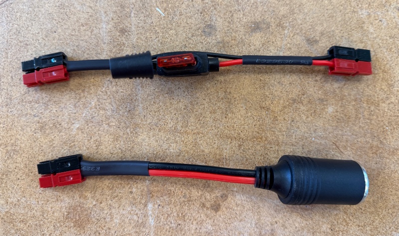 On top is a short cable with an inline automotive blade fuse holder. You can
find the blade fuse holders on Amazon, along with blade fuses in any amperage
you want. Make sure you get large enough wire for your current requirements. For
the bottom cable I bought a female 12V automotive plug with a pigtail, and
crimped powerpoles on the end of it. Anywhere I have a powerpole cable I can now
have an 12V accessory plug. This is particularly useful as a way to connect a
USB-C car charger to a 12V power source.
On top is a short cable with an inline automotive blade fuse holder. You can
find the blade fuse holders on Amazon, along with blade fuses in any amperage
you want. Make sure you get large enough wire for your current requirements. For
the bottom cable I bought a female 12V automotive plug with a pigtail, and
crimped powerpoles on the end of it. Anywhere I have a powerpole cable I can now
have an 12V accessory plug. This is particularly useful as a way to connect a
USB-C car charger to a 12V power source.
A distribution block is a bus bar attached to several fused Powerpole connectors. They typically accept readily available automotive blade fuses, which come in any amperage rating you want. I like the distribution blocks made by West Mountain Radio but they are often out of stock. You can find many other options (of widely varying quality) on Amazon.
There are smaller distribution blocks that forego the fuses and have fewer connectors. These are especially handy for use in the field. If you need a fuse, you can use an accessory cable with an inline blade fuse.
When putting together a go box, adding a couple panel mount powerpole connectors makes it easy to connect an external power source. You could also add panel mount powerpoles and a distribution block to a portable battery box.